Proxmark3 community
Research, development and trades concerning the powerful Proxmark3 device.
Remember; sharing is caring. Bring something back to the community.
"Learn the tools of the trade the hard way." +Fravia
- Logged in as ikarus
- Last visit: Today 11:22:42
- Topics: Posted | New | Active | Unanswered
Announcement
Time changes and with it the technology
Proxmark3 @ discord
Users of this forum, please be aware that information stored on this site is not private.
#1 2023-12-05 20:21:37
Broke the RDV4 USB connector. PCB design or help?
Hi!
I got the RDV4 a few years back, and I broke the Microusb connector, and later got it fixed in a non-professional way. And then it broke again, taking a few millimeters of the wire/line(s) from the board with it, and the soldering was from perfect. Now I cannot really see where the pins should be connected. Is the PCB design of RDV4 available somewhere? Or can someone show me where the D+ and D- should be connected? (I got the GND and VCC already)
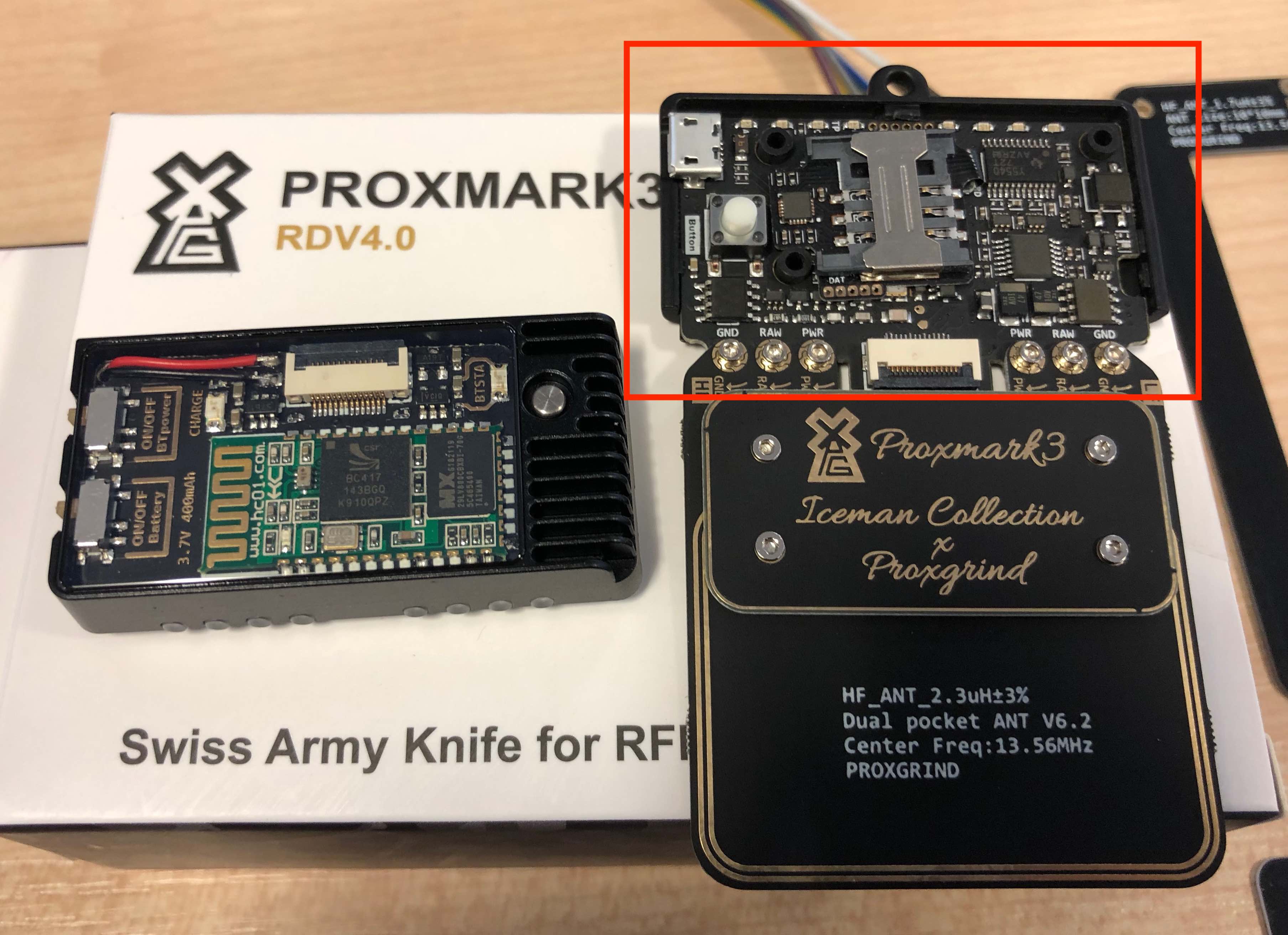
Currently I have some hot glue and large cables over the area to be able to power it, so the best picture I've found is
https://www.ivoidwarranties.tech/img/Pr … /step1.jpg
If someone can mark where D+ and D- should be it would hopefully let me communicate with it (normally) again ![]()
Thanks!
Last edited by tuppkam (2023-12-05 20:22:17)